Fenster der Systemelemente/en: Unterschied zwischen den Versionen
Ferrao (Diskussion | Beiträge) (Die Seite wurde neu angelegt: „The second window is the data sheet of the respective system element and differs according to the element type. It contains the calculation methods for the sys…“) |
Keine Bearbeitungszusammenfassung |
||
| (33 dazwischenliegende Versionen von 3 Benutzern werden nicht angezeigt) | |||
| Zeile 3: | Zeile 3: | ||
{{Navigation|vorher=|hoch=Einzelfenster von Modellkomponenten|nachher=Einzugsgebietsfenster}} | {{Navigation|vorher=|hoch=Einzelfenster von Modellkomponenten|nachher=Einzugsgebietsfenster}} | ||
The system elements in Talsim-NG are filled by two types of windows. | The system elements in Talsim-NG are filled by using two types of windows. | ||
==General | ==General Window of System Elements== | ||
The settings, which are, to a large extent, similar for all elements, are predefined in a general window. This window opens automatically when creating a new system element. It contains the following tabs: | |||
; | ;Key | ||
4-digit unique | : 4-digit unique key of the element; the first letter is determined by the element type. | ||
: Short description of the system element | : Short description of the system element. | ||
; | ;Outflows | ||
: | : Keys of the outflow elements. Depending on the type of element there is the possibility to assign one or more outflow elements. To do so, select the corresponding element from the list on the right side of the window and assign it to the desired outflow using the arrow key. | ||
;Flow direction | ;Flow direction | ||
: Display of the flow direction in the | : Display of the flow direction in the flow network map. This setting has no effect on the calculation. | ||
;Symbol | ;Symbol | ||
Symbol | : Symbol which shall represent the system element in the system plan. For each element type there are different options with a short description of what the symbols are intended for. The symbols have no influence on the calculation of the system element and a differentiation within an element type only serves to improve the clarity of the flow network map. Therefore, each user can make a distinction according to one's own criteria or use the default symbol. | ||
;Description | ;Description | ||
: | : Detailed description of the system element. | ||
<gallery widths=200px mode="nolines"> | <gallery widths=200px mode="nolines"> | ||
Datei: | Datei:Fenster_Systemelemente_Kennung_EN.png|Key | ||
Datei: | Datei:Fenster_Systemelemente_Abläufe_EN.png|Outflows | ||
Datei: | Datei:Fenster_Systemelemente_Fließrichtung_EN.png|Flow direction | ||
Datei: | Datei:Fenster_Systemelemente_Symbol_EN.png|Symbol | ||
Datei: | Datei:Fenster_Systemelemente_Beschreibung_EN.png|Description | ||
</gallery> | </gallery> | ||
Later, this window can be opened by right-clicking on the system element and selecting ''Key'', ''Outflows'' or ''Flow direction'' from the appearing menu, also allowing changes to the settings. | |||
== | ==Properties of System Elements== | ||
The second window | The second window shows the properties of a system element which will differ for each element type. The window contains the calculation methods for the system element, as well as the corresponding characteristics and parameters. | ||
*[[Special:MyLanguage/Einzugsgebietsfenster| | *[[Special:MyLanguage/Einzugsgebietsfenster|Sub-basin window]] | ||
*[[Special:MyLanguage/Einzeleinleiterfenster| | *[[Special:MyLanguage/Einzeleinleiterfenster|Point source window]] | ||
*[[Special:MyLanguage/Transportstreckenfenster| | *[[Special:MyLanguage/Transportstreckenfenster|Transport element window]] | ||
*[[Special:MyLanguage/Verbraucherfenster| | *[[Special:MyLanguage/Verbraucherfenster|Consumer window]] | ||
*[[Special:MyLanguage/Verzweigungsfenster| | *[[Special:MyLanguage/Verzweigungsfenster|Diversion window]] | ||
*[[Special:MyLanguage/Speicherfenster| | *[[Special:MyLanguage/Speicherfenster|Storage window]] | ||
The properties can be opened by double-clicking on the system element or by right-clicking → ''Properties''. | |||
Aktuelle Version vom 30. August 2021, 12:42 Uhr
The system elements in Talsim-NG are filled by using two types of windows.
General Window of System Elements
The settings, which are, to a large extent, similar for all elements, are predefined in a general window. This window opens automatically when creating a new system element. It contains the following tabs:
- Key
- 4-digit unique key of the element; the first letter is determined by the element type.
- Short description of the system element.
- Outflows
- Keys of the outflow elements. Depending on the type of element there is the possibility to assign one or more outflow elements. To do so, select the corresponding element from the list on the right side of the window and assign it to the desired outflow using the arrow key.
- Flow direction
- Display of the flow direction in the flow network map. This setting has no effect on the calculation.
- Symbol
- Symbol which shall represent the system element in the system plan. For each element type there are different options with a short description of what the symbols are intended for. The symbols have no influence on the calculation of the system element and a differentiation within an element type only serves to improve the clarity of the flow network map. Therefore, each user can make a distinction according to one's own criteria or use the default symbol.
- Description
- Detailed description of the system element.
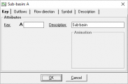
Key
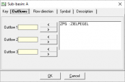
Outflows
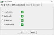
Flow direction
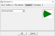
Symbol
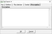
Description


Later, this window can be opened by right-clicking on the system element and selecting Key, Outflows or Flow direction from the appearing menu, also allowing changes to the settings.
Properties of System Elements
The second window shows the properties of a system element which will differ for each element type. The window contains the calculation methods for the system element, as well as the corresponding characteristics and parameters.
- Sub-basin window
- Point source window
- Transport element window
- Consumer window
- Diversion window
- Storage window
The properties can be opened by double-clicking on the system element or by right-clicking → Properties.