In Talsim, a river basin model is constructed following a modular approach. All relevant components and processes of the water resources system are represented by system elements. These elements can be connected like building blocks to represent the complete system along with its interactions.
System Element overview
Each system element has specific properties and methods. It can process defined inputs or hydrological stresses — such as precipitation, water inflow, or pollutant loads — and generates corresponding outputs, such as outflow or sediment transport. The table below provides an overview of all system elements in Talsim, including their key properties, methods, and typical types of input and output.
SystemElement |
Representation of (examples) |
Element Stress |
Element Stress |
Element Methods |
Element Output |
|---|---|---|---|---|---|
Point Source
|
•Catchment outflow •Discharge •Emission of chemical substances •Water input |
•Water inflow
Optional: •Inflow of substances |
|
Water input into the system •TimeSeries •Pattern
Optional: Input of Substances |
•1 Water outflow |
Catchment
|
•Catchment •Grid cell of natural area •Hydrological catchment •River basin •Urban catchment |
•Precipitation •Evaporation •Temperature |
Optional: •Irrigation |
|
1-3 Water outflows Total catchment runoff or division into runoff components: •Surface runoff (urban) •Surface runoff (rural) •Interflow •Interflow (deep) •Baseflow •Groundwaterflow (deep) |
Transport Reach
|
•Collection drain •Open channel •Pipe •River •Stream •Tube |
Optional: •Heat inflow •Heat exchange |
•Water inflow
Optional: •Inflow of substances •Inflow of heat |
|
1-2 Water outflows
|
Diversion
|
•Diversion •Storm-water overflow •Water abstraction system •Weir •Withdrawal |
|
•Water inflow
Optional: •Inflow of substances •Inflow of heat |
|
2 Water outflows |
Consumer
|
•Agricultural water user •Industrial water user •Water supply company •Water works
|
|
•Water inflow
Optional: •Inflow of substances •Inflow of heat |
|
2 Water outflows (if Outflow2 is not connected Losses are lost) |
Storage
|
•Dam •Hydropower plant •Rainwater retention basin •Reservoir •Stormwater retention tank |
Optional: •Precipitation •Evaporation |
•Water inflow
Optional: •Inflow of substances •Inflow of heat |
|
1-3 Water outflows |
Groundwater
|
•Aquifer •Groundwater reservoir |
|
|
|
|
System Outlet
|
|
|
|
|
|


Boundaries of the water resources system

Example for the system boundaries of a study area
A water resources system typically comprises hydrological catchments, watercourses, and engineered infrastructure. These may be subject to operational control based on observed system states. Hydrological drivers such as precipitation and inflow must be considered when defining the model.
System boundaries should be drawn so that all relevant processes and stressors influencing the system can be represented. An initial boundary can often be defined using hydrological catchment limits (e.g., derived from GIS data) and extended as needed. Extension is warranted if processes or data from outside the catchment influence internal dynamics or are needed for calibration — such as streamflow records for setting up operating rules.
Note: System boundaries may be adjusted later during the system’s division into elements. If some sub-catchments are modeled as external inflows via point sources, the defined system boundaries become smaller accordingly.
Division of the system into System Elements
Once system boundaries are set, the model can be broken down into individual system elements.
The way a system is divided depends primarily on the specific objectives of the modeling and the available data.
There are two main approaches to this division: catchment-based and grid-based. Additionally, all relevant hydrological structures must be identified and represented using appropriate system elements — for example, dams as storages, and withdrawals as consumers. Often, several valid configurations may exist.
Preliminary work to define the river basin structure is typically performed using a GIS.
Catchment-based Division
Criteria for the division can be:
•Physical characteristics of the area (topography)
•Localized changes in discharge caused by
oInflows
oPoint sources
oExtractions
•Locations of hydraulic structures
•Location of gauging stations
•Stream type and geometry
The outcome is a set of digital catchment boundaries and stream sections. If the available data leads to a coarse initial division, further refinement may be needed to capture specific processes in greater detail. Below is a comparison between a high-resolution and a low-resolution system representation:
|
|
•Increased importance of hydraulic routing within the stream network. •Runoff concentration parameters reflect only surface, interflow, and baseflow from the relevant sub-catchment. •Flow routing (e.g., flood waves) in streams can be explicitly represented. |
•Simple runoff generation methods often perform better with coarser system representations. •Parameters of the runoff concentration combine runoff from sub-catchments with routing effects in the stream. •Flow routing in streams is barely, if at all, traceable. |
The choice of system element for representing a sub-catchment depends on the modeling goal and available data. A Catchment element performs precipitation-runoff simulations to generate inflows. Alternatively, a Point Source can be used if observed discharge data (hydrographs) are available at the outlet of a sub-catchment. This option is less computationally intensive and can closely replicate observed flow, assuming high-quality input data. However, when forecasting scenarios under changing land use or if time series are insufficient, the Catchment element is preferred. In Talsim, different system elements can be assigned to each sub-catchment based on these considerations. |
 Sub-catchments can be defined via a Rainfall-Runoff Model or can be visualised through a hydrograph at the outlet |
Grid-based Division
In a grid-based division, the area is not subdivided according to catchment boundaries but instead based on a fixed, regular grid of cells. Each cell represents a discrete spatial unit, and the overall model structure is defined by the resolution of this grid. Water is routed from one cell to the next according to predefined flow directions, typically derived from a digital terrain model (DTM).
Flow component transfers are handled as follows:
•Surface runoff: Added to the runoff generation in the downstream cell and treated as additional precipitation.
•Interflow: Routed to the interflow storage cascade of the next cell.
•Baseflow: Routed to the baseflow storage cascade of the next cell.
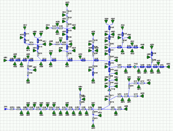
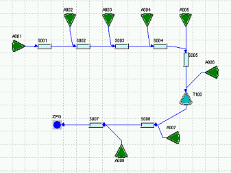
Flow network

Example for a project area and the abstraction as system plan
The flow network describes the flow relations between the individual system elements. This requires the subcatchment division and the waterbody network, respectively the grid-based division and the grid of flow directions (from a DTM). Furthermore, the corresponding inflow and outflow elements must be identified entirely for the depicted water infrastructure.
In order to build the flow network, system elements are created and connected according to the flow direction.
The flow network will be illustrated by a System map in the user interface.