Systemplan/en: Unterschied zwischen den Versionen
Keine Bearbeitungszusammenfassung |
Keine Bearbeitungszusammenfassung |
||
| Zeile 65: | Zeile 65: | ||
===Construct | ===Construct Flow Network Automatically=== | ||
===Flow network overview on/off=== | ===Flow network overview on/off=== | ||
Version vom 20. November 2020, 12:58 Uhr

The flow network map provides a schematic overview of the river basin model. The system elements are represented by the symbols and the flow relations between them (system logic) are illustrated by the arrows.
When a scenario is activated, the corresponding flow network map opens automatically. An empty scenario contains an empty flow network map with the system outlet element as default.
Create New System Elements
To create new system elements, drag and drop them from the system elements bar onto the flow network map. The general system elements window, where a unique key must be entered, automatically opens. All other settings and descriptions in this window can be filled in later.

The desired system element is selected...

...and dragged onto the flow network map while holding down the left mouse button.

The element can then be dropped at the desired position (drag&drop).
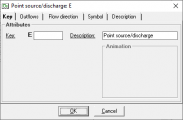
Finally, a unique key and a clear description should be assigned.


Moving System Elements
Existing system elements can be moved on the flow network map with drag and drop.
Connecting System Elements
To connect two existing system elements, the start element is dragged onto the target element, while holding down the Ctrl-key. If an element should hold several outflows, this process is performed several times. The first connection will automatically become outflow1, the second outflow2, and so on. If the sequence is to be changed, the connections must first be deleted and then recreated in the desired sequence. Alternatively, right-clicking on the start element -> Outflows can also be used to assign outflow elements and, thus, create a connection (see Outflows Tab).
Select element with the left mouse button. Press and hold <CTRL> key.

Drop the element on the target element, while still holding down the <CTRL> key and the left mouse button

The flow relationship is set up.


Deleting Connections Between System Elements
Similarly to the procedure for creating new connections, existing connections can be deleted by dragging the start element to the target element while holding down the Ctrl-key. Existing connections can also be deleted by right-clicking the start element -> Outflows (see Outflows Tab).
Selecting System Elements
System elements within a rectangular area of the flow network map, can be selected, using the mouse. Right-clicking on a system element -> Select upstream elements allows you to select all system elements upstream of the selected element. Selecting system elements can be useful when using the automatic alignment of elements in the system plan (Menu View -> Align elements -> Top,...) or for editing a list of elements (Menu System -> Edit elements)
Moving the display area in the flow network overview

. The red frame shows the currently displayed section and where it is located in the overall system plan. It can be moved by Drag&Drop. With very large system plans, it is possible that not the whole system plan fits on the screen and only a section is displayed. In the system plan overview in the lower left corner the whole system plan is displayed in small size and the current section is marked with a red frame. The displayed section can be moved by dragging and dropping the red frame in the system plan overview.
Aligning Elements
Flow network
Checking flow network

Via Menu System -> Flow Network Map -> Flow Network -> Check you can check if the system logic of each system element has connections according to its specifications. Missing outlet or inlet elements are displayed in the appearing window Error-Log: System Logic window.